
In July 2020, a new standard for double data rate (DDR) memory was announced. The exciting DDR5 technology promises higher data rate with reduced power consumption. This is a promise that is familiar to serial link designers. However, like most things in life, there is no free lunch. The advances for lower power and higher speed come with an increase in design complexity. The most notable difference between DDR5 and previous generations is the introduction of decision feedback equalization, which is a technique used in serial link systems to improve the integrity of received signals.
In the wake of the new technology, this article examines some fundamental signal integrity concepts in the context of DDR5. The first section introduces the eye diagram: a metric to determine the goodness of signal integrity. The second section describes root causes of signal integrity problems by examining the single pulse response. The third section prescribes possible solutions to the resulting signal integrity problems.
Eye Diagram to Determine Signal Integrity
The eye diagram is a primary metric for evaluating the signal integrity of a channel. It is created by appropriate processing of received pseudo random binary sequence (PRBS) through a channel. To create an eye diagram in the context of the “write” cycle of memory operation, the controller (transmitter) sends PRBS through a channel to reach the memory module (receiver). The received PRBS pattern at the memory module is divided into segments with the same time interval. These segments with identical time interval are then stacked on top of each other to create an eye diagram.
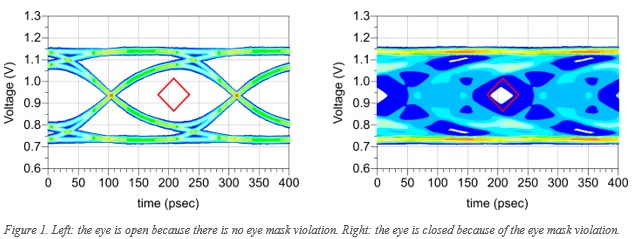
In Figure 1, there are two eye diagrams in blue and eye masks in red. By comparing the eye diagram at the output of the channel to an eye mask, one determines the signal integrity of the channel. The eye mask is a graphical representation of the receiver’s threshold. The eye mask shows the acceptable timing and amplitude of the received signal for a given bit error ratio (BER).
As shown on the left of Figure 1, the eye is open. The channel has good signal integrity when there is no overlap between the output eye diagram and the eye mask. If the output eye diagram does not overlap with the eye mask, the receiver can determine a digital one or digital zero based on the received analog voltage level and timing. On the other hand, if there is an eye mask violation (as shown on the right of Figure 1) the eye is closed. A digital one or digital zero cannot be distinguished at the receiver.
The eye diagram gives engineers a metric for the performance of a given channel. When there is a closed eye at the receiver, one needs additional analysis techniques to identify the root cause of the eye closure.
Frequency-Dependent Loss and Reflection in DDR5
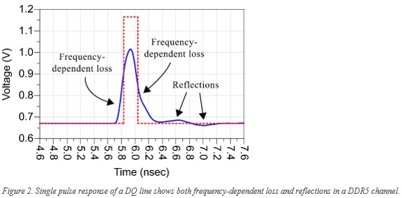
The main concerns specified in DDR5 standard are reflections and frequency-dependent loss [1]. Figure 2 shows the single pulse response of a DQ line from the controller to the memory module. The single pulse response is the received waveform at the memory module when a single pulse, a digital one, is sent from the controller.
In Figure 2, the red dotted line is the ideal case where no reflections or frequency-dependent loss are in the channel. In blue, one observes the frequency-dependent loss of the channel as the spreading of the ideal pulse. The reflections in the channel come later in time. Because the spreading of the single pulse and the reflections can interfere with other pulses, one often refers to them as inter-symbol interference (ISI) [2].
The ISI caused by frequency-dependent loss is common in serial link channels while the reflection problem caused by impedance discontinuities is quite unique to DDR.
Decision Feedback Equalization in DDR5
If the root cause of the signal integrity problem is frequency-dependent loss, the most straight-forward solution is to reduce the length of the channel or use low loss material in fabrication. To minimize the amount of reflections, traces should be designed with controlled impedance. If the eye remained closed with appropriate channel length, fabrication material, and impedance control, equalization at the receiver can help further improve/open the eye at the receiver.
In DDR5, four-tap decision feedback equalization (DFE) was specified to mitigate the loss and reflection without amplifying noise [1]. With each tap representing one unit-interval, the four-tap DFE corrects up to four unit-intervals after the current received bit. As the name suggests, the decision feedback equalization algorithm makes a decision on each received bit and feeds a modified version of the bit back to the receiver.
In the DFE algorithm, the received analog waveform first arrives at the symbol detector. The symbol detector decides whether the received analog waveform represents a digital one or a digital zero. If the detected symbol is a digital one, a scaled version of the analog waveform would be added to the original to emphasize the next digital zero. If the detected symbol is a digital zero, a scaled version of the analog waveform would be added to the original to emphasize the next digital one.
Shown on the left of Figure 3 is an almost closed eye. By applying DFE, the almost closed eye can be opened. As shown in the right of Figure 3, DFE algorithm successfully opens the almost closed eye. Another unique feature of a DFE equalized eye is the kinks before and after the eye opening.

As the data rate increases, one sees a convergence of technologies between serial link and DDR. Before DDR5, no equalization was needed to have a decent eye opening at the receiver. With the push for higher speed and lower power consumption, equalization has become a necessity for an adequate eye opening.
Although it is comforting to have an equalizer at the receiver to improve the eye, one still needs to properly engineer the channel loss and trace impedance so that the equalization can have the most positive impact on the system performance.
To better understand the trade-off between different channel designs and equalization capabilities, the use of electronic design automation (EDA) software as a virtual prototyping environment has become a necessity as well. By combining the results of virtual prototyping and measurements of the real designs, one forms a robust design workflow that tackles the new and exciting technology.
References
[1] JEDEC Solid State Technology Association, DDR5 SDRAM, JESD79-5. Arlington, VA, 2020
[2] Eric Bogatin, Signal Integrity - Simplified. Prentice Hall, 2009.