
A TDR (time domain reflectometer) is an instrument that probably has the fastest rise time of any instrument in your lab, yet you can test its accuracy using a DC Ohmmeter.
What the TDR Measures
In all high-speed channels, reflections are bad. We try to engineer a channel to reduce the reflections, which all contribute to inter-symbol interference (ISI).
But in a TDR, reflections are our friend. We use the reflections of a signal when it encounters a change in the instantaneous impedance as the basis of operation of the instrument. The TDR also leverages the finite propagation speed of the signal. This transforms the location of the discontinuity into a time delay of when the reflection is measured at the source.
There are two important elements in a TDR instrument: a very fast step edge generator and a sampling scope to measure the voltage near the launch of the signal. Figure 1 shows how of these two elements are used to transmit and measure the reflections from a device under test (DUT).

The fast edge is launched into the DUT and propagates down the length of the interconnect. Wherever the edge encounters a change in the instantaneous impedance, a reflected signal is created, propagating in the backward direction toward the source. It is detected when the reflected edge makes its way back to the sampling scope. The magnitude of the reflection and when it is measured encode the information about the magnitude of the impedance change and its location.
From the signal’s perspective, it doesn’t matter what physical structure creates the change in instantaneous impedance. It could be from a change in geometry of a transmission line, and it can also be a discrete resistor in series or in shunt.
A TDR is sensitive to series resistance and shunt resistance
If the interconnect is uniform, the signal sees a constant instantaneous impedance between the signal and return path as it propagates down the line. If the edge encounters a discrete series resistance it sees this in series with the instantaneous impedance of the transmission line. This higher instantaneous impedance creates a small reflection. But, the rest of the path has no change in impedance, so there is no further reflection.
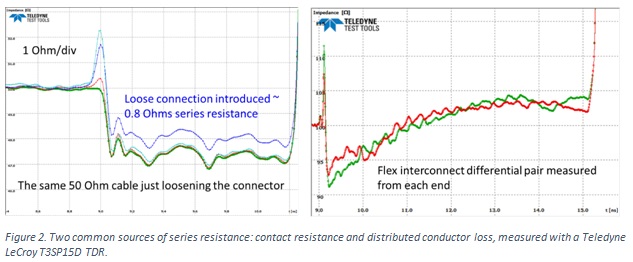
The impact of a small series resistance is to create an offset in the distributed impedance of the transmission line. This can arise, for example, when there is contact resistance in the connector due to a dirty connector or a loose connection.
If there is high series resistance in the interconnect, due to a narrow signal conductor, for example, the impedance will appear to gradually increase as the signal propagates down the line. The way to distinguish a geometry impact on the impedance or a series resistance is to measure the DUT from each end. If the instantaneous impedance increase is due to a distributed series resistance, the impedance profile will look “uphill” in both directions. Figure 2 shows examples of these two effects in transmission line structures.
When the resistance is a shunt, across the signal and return path, it is in parallel with the instantaneous impedance of the transmission line. If this resistor is placed at the end of the transmission line, the resistor shorts the open, and its resistance dominates the instantaneous impedance.
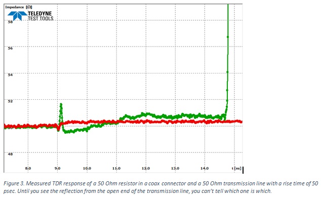
The signal cannot tell the difference between the instantaneous impedance of a uniform 50 Ohm transmission line and a 50 Ohm resistor between the signal and return at the end of the line. Figure 3 shows the TDR response from two structures; one is a 50 Ohm transmission line and one is a 50 Ohm shunt resistor. Both are engineered with small discontinues at the launch. It is only by waiting to see the reflection from the open at the end of the coax cable that you can tell which is which.
TDR from discrete resistors
The instantaneous impedance of a resistor in parallel with an open is its resistance. In principle, if we measure the TDR response of a discrete shunt resistor, we should see just the resistance of the resistor.
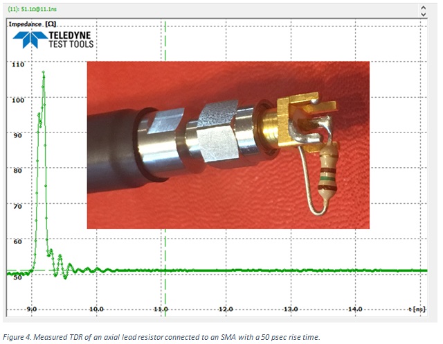
In practice, the connection of the discrete resistor to a coaxial connector, like an SMA, will always result in a large discontinuity. Due to the long leads, the discontinuity will always be high, looking like an inductive discontinuity. An example of the measured TDR response from a 50 Ohm axial lead resistor soldered on an SMA connector is shown in Figure 4.
We can model the connection as a short, high impedance, uniform transmission line, with the 50 Ohm SMA on one side and the resistor on the other. If the short discontinuity is lossless, there will be reflections from the front end and back end of the discontinuity. And, the reflection from the back end will rattle around inside the discontinuity, reflecting off of each end.
If we wait long enough (roughly 5 round trip times) for all the reflections to die out, we will see the net reflection from the change of impedance between the 50 Ohm of the source and the resistance of the discrete resistor. This principle can be illustrated in a simple simulation. Figure 5 shows the simulated TDR response from a 0.1 nsec long 200 Ohm transmission line in series with a 75 Ohm ideal resistor. The rise time is 35 psec.

You can see the multiple reflections inside the 200 Ohm transmission line. Its TD = 0.1 nsec. The round-trip delay between the reflection from the front and from the back of the 200 Ohm transmission line is 2 x TD = 0.2 nsec. Even with such a high impedance difference, after 5 x round trip delay = 1 nsec, all the reflections have died away and the measured impedance is the impedance of the resistor, 75 Ohms.
This suggests a powerful way of testing the accuracy of a TDR using discrete resistors.
Verifying the accuracy of a TDR with Resistors
I took a selection of axial lead, ¼ watt carbon resistors with values of roughly 10 Ohm, 30 Ohm, 50 Ohm, 70 Ohm, 100 Ohms, 150 Ohms and 330 Ohms, and soldered them to SMA connectors. I was not trying to engineer a low launch discontinuity. I measured the resistance between the signal pin and outer shield of the SMA with a Keithley 196 System DMM, which has a NIST traceable absolute accuracy of 0.1% in resistance. I was careful to eliminate the artifact of the 0.3 Ohm series resistance of the test leads.
Generally, it is difficult to reduce the contact resistance to less than 0.1 Ohms, which contributes an error at the 1% level for the 10 Ohm resistor.
When I measured these SMA mounted resistors with my TDR, I measured the responses shown in Figure 6. In this example I used a 50 psec rise time.
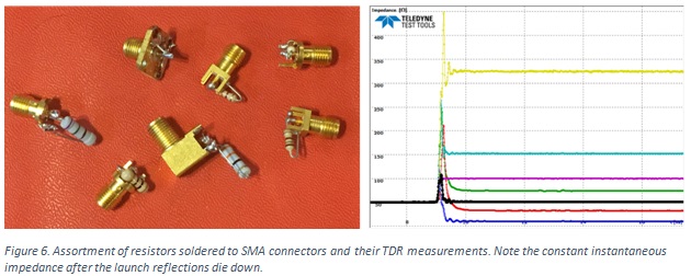
While they each have a very large discontinuity at the launch, if we wait for these initial reflections to die down, the final, long time impedance as measured by the TDR is very close to what is measured with the DMM. Here is a summary of the differences between the DC DMM Ohmmeter measurements and the 35 psec TDR measurements:
DMM Resistance TDR resistance relative error
R = 9.96 Ohms 10.1 Ohms 0.14 Ohms/10 Ohms = 1.4%
R = 32.3 Ohms 32.5 Ohms 0.2 Ohms/32.2 = 0.6%
R = 50.8 Ohms 50.9 Ohms 0.1/51 Ohms = 0.2%
R = 74.1 Ohms 73.8 Ohms 0.3 Ohms/74 Ohms = 0.4%
R = 100.0 Ohms 99.7 Ohms 0.3/100 = 0.3%
R = 153.4 Ohms 151.8 Ohms 1.6 Ohms/153 = 1.0%
R = 329 Ohms 324 Ohms 5 Ohms/329 = 1.5%
Near 50 Ohms, the absolute accuracy is less than 1%.
Conclusion
If you want confidence in the accuracy of your TDR, it’s easy to build a few samples of resistors, measure their resistance with a TDR and compare to their DC resistance. As long as you wait long enough for all the launch discontinuities to die out, you should measure the same resistance with the DMM as with the TDR. This is a test of the calibration accuracy of your TDR. It is one step every TDR user should take to gain confidence in the accuracy of the instrument.
Recent Comments
In this article it is said that a...
Thanks much. Excellent. Some typos... Fig. #s are...
The capacitors between the Vdd and I/O pin...
The current of high-low should be due to...
very nice article!...